066 Topography to Follow Floor
Chris McKeown / July 1, 2025
Topography Tools
Overview
Topography to Follow Floor is the inverse of 065 Floor to Match Topography. Instead of moving the floor to match the ground, this tool reshapes the topography to follow the floor. It removes all existing topography points that fall within the floor's footprint, then adds new points along the floor perimeter and at its vertices at the underside elevation of the floor (position minus thickness). Intermediate perimeter points are interpolated every 2 feet to create a smooth terrain transition under the slab edge. After running, manual adjustment of secondary points may be needed to refine the result.
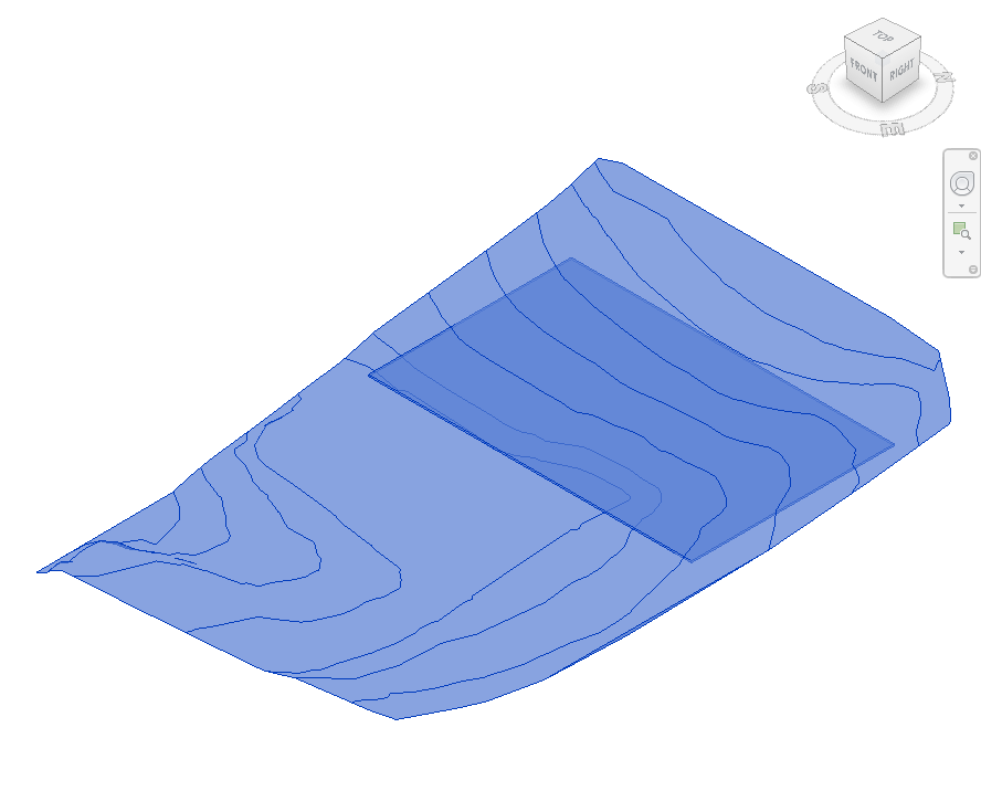
Table of Contents
Key Features
- Removes all existing topography points within the floor's XY footprint polygon
- Adds perimeter points at the floor's bottom elevation (floor Z minus floor thickness)
- Interpolates additional perimeter points at 2-foot spacing for a smooth terrain edge
- Supports both legacy TopographySurface (Revit 2023 and earlier) and Toposolid (Revit 2024+)
- Works on Floors and Footprint Roofs
- Uses
TopographyEditScopefor safe Revit topology editing - Post-run manual point adjustment supported — secondary points can be added or removed as needed
Requirements
- Must be run from a 3D View
- Must be run in a project document (not a Family environment)
- Select both the floor (or roof) and the topography before running
- The floor's Slab Shape Editor must be enabled (not slope-controlled) so vertices can be read
- For Toposolid support, Revit 2024 or later is required
Running the Tool
Launch
Find Topography to Follow Floor on the Bonus Tools Ribbon or use 115 Search Tools.

Step 1 — Open a 3D View
Navigate to a 3D view so both the floor and topography are visible and selectable.

Step 2 — Select Floor and Topography
Hold Ctrl and select both the floor (or footprint roof) and the topography surface (or Toposolid).
The tool determines element types automatically. Only the first floor and first topography found in the selection are processed.
Step 3 — Run the Tool
Click Topography to Follow Floor on the Bonus Tools Ribbon. The tool runs automatically with no dialog.
The operation proceeds in three stages:
- Collect floor vertices — reads all sub-element vertices from the floor and computes their Z offset by subtracting the floor thickness.
- Interpolate perimeter points — adds intermediate points between each pair of adjacent floor vertices at approximately 2-foot intervals along the perimeter.
- Modify topography — deletes all existing topography points within the floor's XY polygon, then adds the new perimeter point list to the topography.
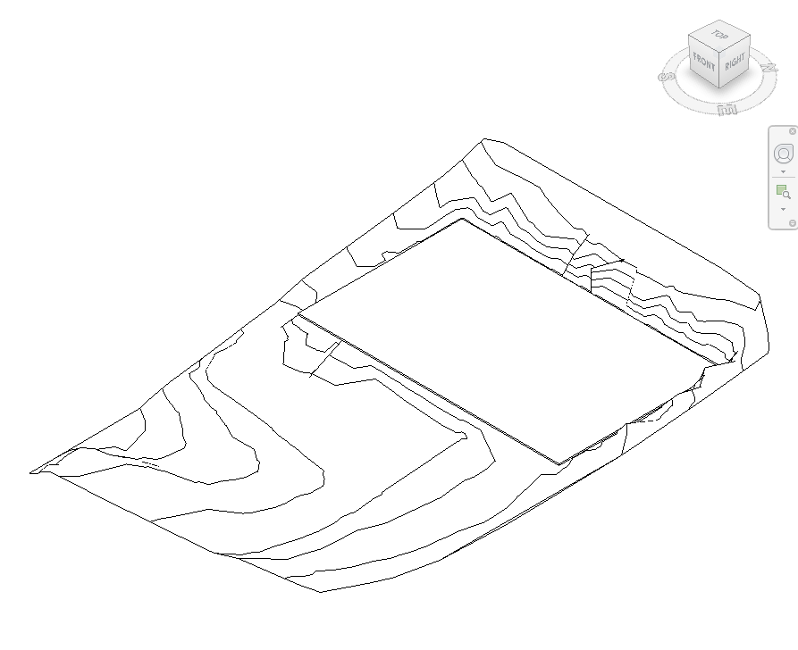
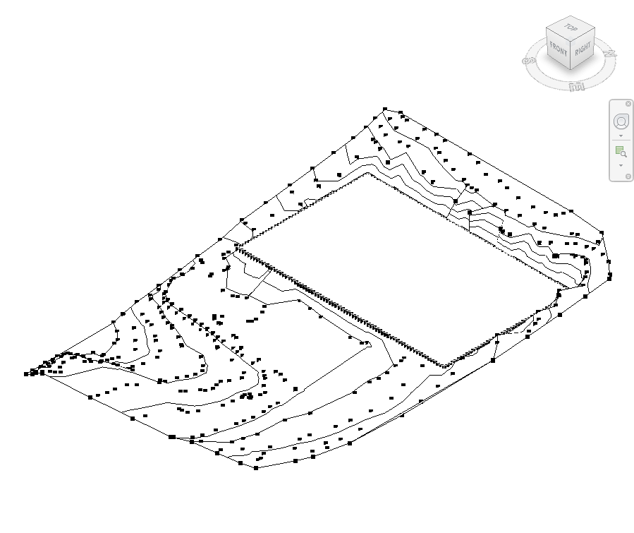
Below: before (left) and after (right) — the topography is reshaped with dense perimeter points following the floor boundary.
Step 4 — Adjust Secondary Points if Needed
After the tool completes, inspect the topography around the floor perimeter. You may need to add or remove secondary points to refine the transition between the modified area and the surrounding terrain.
Use Edit Surface on the topography to add, move, or delete individual points as required.
Tips and Best Practices
- Use the companion 065 Floor to Match Topography for the inverse workflow — adjusting the floor to match the terrain instead.
- Inspect the result around the floor boundary. The interpolated points create a smooth perimeter edge, but the terrain transition beyond the floor edge depends on the existing topography points. Adjust these manually after running.
- Thick floors produce lower insertion points. The tool subtracts the full floor thickness from each vertex Z position. Verify the floor type thickness is set correctly before running — an incorrect thickness produces terrain points at the wrong elevation.
- Re-run after updating the floor shape. If the floor boundary or sub-elements change, re-run the tool to refresh the topography. The existing points within the footprint are deleted and replaced each time.
- Do not use on slope-controlled floors. The Slab Shape Editor must be readable to extract vertex positions. Slope-controlled floors have locked slab shapes.
- Manual secondary points are preserved on re-run only if outside the floor polygon. Any topography points you add inside the floor footprint will be deleted if you re-run the tool.
Common Use Cases
Basement or podium cut — When a basement slab sits below existing grade, reshape the topography to follow the underside of the ground floor slab, accurately representing the cut into the terrain.
Green roof integration — On a planted roof structure at ground level, adjust the topography to meet the underside of the roof deck so site sections and elevations show the correct relationship.
Retaining wall coordination — Use the tool to create a topography profile that follows a tiered floor system, showing each terrace level's relationship to the ground surface.
Civil coordination — After receiving a revised floor plan from the structural engineer, re-run the tool to update the topography so the landscape model stays coordinated with the structural slab positions.
Troubleshooting
"Please go to a 3D View before running this tool." The active view is not a 3D view. Open a 3D view and retry.
"No topography or floor found." The selection does not contain both a floor (or roof) and a topography (or Toposolid). Ensure both element types are selected before running.
"Action not available in the Family environment." This tool only runs in a project document.
Topography looks incorrect after running The perimeter interpolation is based on the floor's sub-element vertices. If the floor does not have the Slab Shape Editor enabled, the tool reads only the boundary corner points. Enable the Slab Shape Editor on the floor first for better vertex coverage.
Points appear at the wrong elevation The tool computes insertion Z as vertex position minus floor thickness. If the floor thickness parameter is incorrect (e.g. a compound floor with an override), the resulting elevation will be off. Verify the floor type and thickness before running.