065 Floor to Match Topography
Chris McKeown / July 1, 2025
Topography Tools
Overview
Floor to Match Topography modifies the sub-element points of a selected floor (or footprint roof) so that each vertex aligns with the elevation of the topography directly below or above it. The tool uses ray-casting from the active 3D view to find the highest topography intersection point at each floor vertex, then applies the corresponding elevation offset. It also adds topography surface points to the floor so the floor profile precisely follows the terrain contour. A progress bar with a Cancel button allows you to stop the operation mid-way on large models.
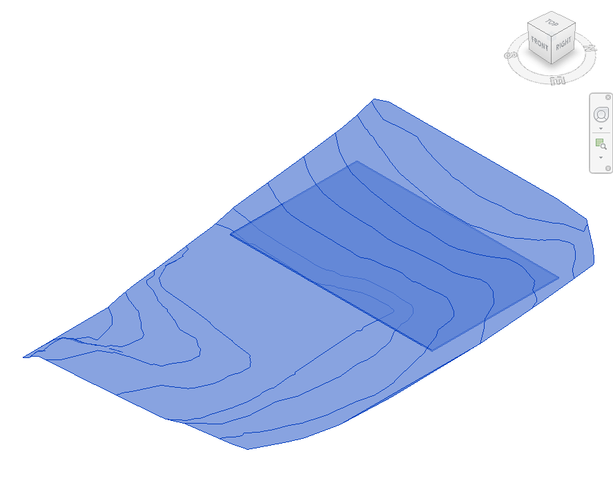
Table of Contents
Key Features
- Adjusts every floor sub-element vertex to match topography elevation via ray-casting
- Adds topography surface points directly to the floor as additional sub-modify points
- Supports both legacy TopographySurface (Revit 2023 and earlier) and Toposolid (Revit 2024+)
- Works on Floors and Footprint Roofs
- Progress bar with Cancel button — safe to stop on large models
- Automatically enables the Slab Shape Editor if it is not already active
- Handles Revit version differences in slab shape API across 2019–2025+
Requirements
- Must be run from a 3D View — the tool uses the active view for ray-casting geometry
- Must be run in a project document (not a Family environment)
- Select both the floor (or roof) and the topography before running — both elements must be in the active selection
- The floor must not be slope-controlled — the Slab Shape Editor must be available (not locked by a slope parameter)
- For Toposolid support, Revit 2024 or later is required
Running the Tool
Launch
Find Floor to Match Topography on the Bonus Tools Ribbon or use 115 Search Tools.
Tip: Use 026 Topography Surface Edge first to align the floor boundary to the topography edge before running this tool. This ensures the floor footprint exactly matches the topography shape before sub-elements are adjusted.
Step 1 — Open a 3D View
Navigate to a 3D view. The tool uses this view for ray-casting, so the topography and floor must both be visible in the active view. Turn off section box clipping if it would obscure either element.

Step 2 — Select Floor and Topography
Select both the floor (or footprint roof) and the topography surface (or Toposolid). You can hold Ctrl and click each element, or use a box selection that captures both.
The tool identifies each element type automatically — it does not matter which order you select them. Only the first floor and first topography found in the selection are used.
Step 3 — Run the Tool
Click Floor to Match Topography on the Bonus Tools Ribbon. A progress bar appears showing the number of vertices being processed.
The tool works in two passes:
- Vertex adjustment — For each existing floor sub-element vertex, a ray is cast upward and downward to find the topography surface. The vertex elevation is set to match the highest intersection point found.
- Point addition — All topography surface points are added to the floor as additional sub-modify points, giving the floor a detailed terrain profile.
Click Cancel at any time to stop processing. Changes already applied are kept.
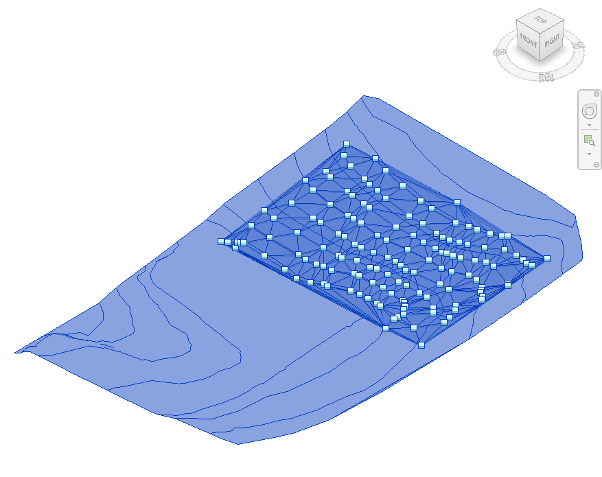
Step 4 — Review the Result
After the tool completes, inspect the floor in the 3D view. The floor surface should follow the topography contour. The floor will now show a dense grid of sub-modify points (green squares) matching the terrain shape.
Tips and Best Practices
- Run 026 Topography Surface Edge first. This tool aligns the floor boundary to the topography edge, ensuring the floor footprint is already the correct shape before sub-elements are adjusted.
- Use the companion tool 066 Topography to Follow Floor for the inverse operation — modifying the topography to match a floor.
- Ensure both elements are visible in the 3D view. Ray-casting only hits geometry that is visible in the active view — hidden elements will produce missed intersections.
- Disable section box clipping before running. A section box that cuts through the floor or topography can cause incorrect ray-casting results.
- Do not use on slope-controlled floors. If the floor has a slope parameter applied, the Slab Shape Editor is locked and sub-elements cannot be modified. Remove the slope parameter first.
- On large topographies, expect longer processing times. The second pass adds one point per topography vertex — models with dense topo meshes can take several minutes. Use Cancel if needed and add points manually for problem areas.
Common Use Cases
Earthworks and podium slabs — Adjust a ground-level slab to follow the natural terrain contour before site cut-and-fill is applied, giving an accurate representation of the slab on grade.
Sloped site floors — On hilly sites, align interior ground-floor slabs to the topography elevation so that section cuts and elevations show the correct relationship between structure and ground.
Footprint roof on terrain — Apply to a footprint roof over a landscape structure (e.g. green roof, underground car park lid) to have the roof surface conform to the surrounding terrain.
Coordination with civil engineers — After receiving an updated topography from a civil engineer, re-run the tool to refresh the floor sub-elements and keep structural levels aligned with the revised terrain model.
Troubleshooting
"Please go to a 3D View before running this tool." The active view is not a 3D view. Open a 3D view and retry.
"Cannot Modify Sub Elements. Is the Floor controlled by a Slope?" The floor or roof has a slope applied via a parameter, which locks the Slab Shape Editor. Remove the slope definition from the floor type or instance before running.
"No topography or floor found." The selection does not contain both a floor (or roof) and a topography (or Toposolid). Ensure you have selected exactly one of each before running the tool.
"Action not available in the Family environment." This tool only runs in a project document. Close the Family Editor and open a project file.
Floor vertices do not intersect topography If the floor is positioned far above or below the topography, the ray may not find an intersection. Verify that the floor and topography overlap in XY extent and that the topography geometry is not hidden in the active 3D view.