031 Setting Out Points
Chris McKeown / July 1, 2025
Time Saving
Overview
Setting Out Points places a Generic Model family instance at each corner point of structural elements in your Revit project. Each placed point stores the real-world X, Y, and Z coordinates (accounting for project location and true north), the element type it was extracted from, and a sequential point number — all in shared parameters. The companion Renumber SOPs tool then re-sequences the point numbers across the entire project. Together these tools automate the preparation of setting-out point schedules for structural construction.
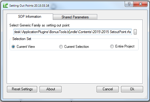
Table of Contents
Key Features
- Extracts corner geometry from Structural Columns, Structural Framing, Structural Foundations, Floors, Ramps, and Walls
- Places a Generic Model family instance at each corner point with correct XYZ coordinates
- Applies the project location transform (true north rotation + base point offset) so stored coordinates match real-world survey values
- Three point-set modes: All Points (every corner vertex), Upper Points (highest Z per XY position), or Lower Points (lowest Z per XY position)
- Three scope options: Current View, Current Selection, or Entire Project
- Writes coordinates and metadata into seven configurable shared parameters on each placed family
- Default shared parameter GUIDs bundled with the tool — compatible with the included
2016_SetoutPoint.rfafamily - Custom shared parameter GUIDs can be entered for company-specific families
- Reset Settings button restores all GUIDs to the bundled defaults
- Companion Renumber SOPs tool sequentially renumbers all placed points with a "SOP " prefix
- Progress bar with Cancel button; rolling back all changes on cancel
- Blocked in the Family Editor — runs in project documents only
Requirements
- Must be run in a project document (not a Family document)
- The Generic Family (
.rfa) file must be accessible on disk — the tool loads it automatically if not already in the project - The Generic Family must contain two types — the tool uses the second type (
symbols[1]) for placement - Seven shared parameters must exist in the family with the correct GUIDs (defaults provided)
- A valid Kiwi Codes Bonus Tools licence must be active
Running the Tool
Launch
Find Set SOPs on the Bonus Tools Ribbon or use 115 Search Tools to launch the Setting Out Points dialog.
Step 1 — Select the Generic Family
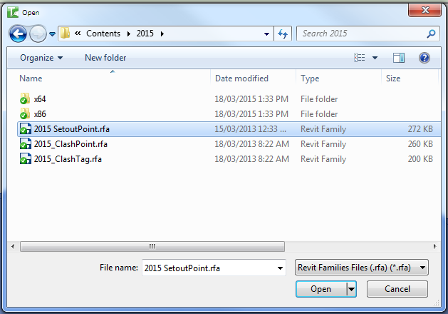
On the SOP Information tab, the Generic Family field shows the path to the setting-out point family file (.rfa). The default path points to 2016_SetoutPoint.rfa included with Bonus Tools.
Click the browse button at the right end of the field to navigate to a different family file if your project uses a custom setting-out point family. The path is remembered between sessions.
The family must contain two types. The tool places instances using the second type in the family's symbol list.
Step 2 — Choose the Selection Set
In the Selection Set group, choose which elements to process:
| Option | What is processed |
|---|---|
| Current View | All structural elements visible in the active view (default) |
| Current Selection | Only elements selected before launching the tool |
| Entire Project | All structural elements across the entire project |
Step 3 — Choose the Point Set
In the Point Set group, choose which corner vertices to use:
| Option | Behaviour |
|---|---|
| All Points | Every unique XYZ corner vertex of each element's solid geometry |
| Upper Points | For each unique XY position, only the vertex with the highest Z value |
| Lower Points | For each unique XY position, only the vertex with the lowest Z value |
Use Upper Points to mark top-of-slab or top-of-column positions; use Lower Points to mark base or foundation levels.
Step 4 — Verify Shared Parameters (optional)
Switch to the Shared Parameters tab to review the seven GUID fields. These must match the shared parameters defined in your setting-out point family.
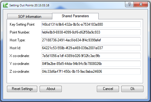
| Field | Default GUID |
|---|---|
| Key Setting Point | f48cd131-b9b6-432a-8b5c-a7534183a880 |
| Point Number | febfe8b9-6938-4099-8cf6-d62f58a9c933 |
| Host Type | 27188736-2491-4ac8-b634-8f4c9399afef |
| Host Id | 64221c53-558b-4f29-a469-039a2001a037 |
| X co-ordinate | 7a5d1056-a1df-4389-b026-9f32fc3ac5fb |
| Y co-ordinate | 84f9a2be-85d5-44da-94b9-fc5b7808026b |
| Z co-ordinate | 04c33d6a-f7f1-450c-8b15-9ac9aba24606 |
Click Reset Settings at any time to restore all GUIDs to the defaults above.
Step 5 — Run and monitor progress
Click OK. A progress bar appears showing how many elements have been processed. Click Cancel at any time to roll back all changes and return the project to its original state.
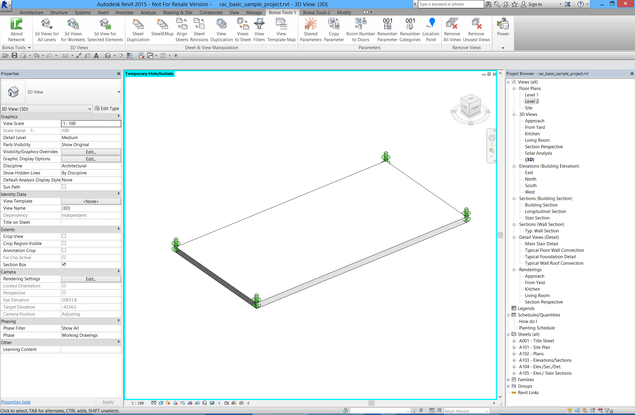
When complete, all corner points of the selected structural elements have a Generic Model family instance placed at the exact XYZ coordinate. Each instance has its shared parameters populated with:
- Point Number — sequential integer assigned during placement
- Host Type — element category (e.g.
Floors,StructuralColumns) - Host Id — the Revit element ID of the source element
- X / Y / Z co-ordinate — project-location-adjusted survey coordinates
Renumber SOPs
After placing setting-out points, run Renumber SOPs from the Bonus Tools Ribbon to assign clean sequential numbers to all placed points.
The tool scans for all instances of the setting-out point family in the project and writes SOP 1, SOP 2, SOP 3, ... into the Point Number shared parameter. A progress bar tracks the renumbering; cancelling rolls back all changes.
Renumber SOPs renumbers all instances of the family across the entire project, regardless of the scope used when placing them. Run it after completing all placements to get a clean sequential sequence.
Tips and Best Practices
- Use Upper Points for top-of-structure setting out. Upper Points gives you one point per column grid intersection at the top elevation — ideal for slabs and column caps.
- Use Lower Points for foundation setting out. Lower Points gives you base coordinates for pile caps, footings, and wall foundations.
- Run on Current Selection for targeted placement. Select only the elements you want before opening the tool to avoid processing the entire model and creating unwanted points.
- Renumber after every batch. If you run Set SOPs multiple times (e.g. first for columns, then for walls), run Renumber SOPs after each batch or once at the end to get a clean, contiguous sequence.
- Use a custom family with two types. The two types allow you to visually distinguish between major and minor setting-out points in 3D views. Manually change individual instances to the other type after placement to mark key control points.
- Check project location before running. The stored X/Y/Z values use the project location transform (true north + base point). Verify your Project Base Point and Site coordinates are correctly set before generating setting-out data.
- The family is auto-loaded. If the setting-out point family is not in the project, the tool loads it from the path in the Generic Family field automatically. Ensure the
.rfafile is accessible from the path shown.
Common Use Cases
Structural column setting-out schedule — Select all structural columns, run Set SOPs with Upper Points to place markers at top-of-column, then run Renumber SOPs. Export the resulting Generic Model schedule to give to the site team.
Foundation setting-out coordinates — Filter to Structural Foundations in a plan view, select them all, run Set SOPs with Lower Points to capture the base elevation of each footing. The stored Host Id links each point back to its source element.
Floor slab corner verification — Run Set SOPs on the Entire Project with Upper Points to capture every slab edge corner in one pass. Compare the generated schedule against the surveyor's design coordinates.
Multi-level setting out — Run Set SOPs per level by setting active view to each floor plan and using Current View scope. All points at each level accumulate in the project; renumber once at the end.
Topping out report — After structural elements are complete, run Set SOPs and export the schedule as a snapshot of as-designed corner coordinates for the structural engineer's topping-out report.
Troubleshooting
"Action not available in the Family environment." The tool was launched while a Family document was active. Close the Family Editor and run from within a project document.
"No elements found." The selected scope (Current View, Current Selection, or Entire Project) contains no structural elements matching the supported categories (Structural Columns, Structural Framing, Structural Foundations, Floors, Ramps, Walls). Verify the scope and selection, then try again.
"The required shared parameters X, Y, Z, Host_Id, Host_Type and Point_Number are missing." The Generic Family does not contain shared parameters matching the GUIDs on the Shared Parameters tab. Either switch to a compatible family or update the GUIDs to match your company family's shared parameters. Use Reset Settings to restore defaults for the bundled family.
"No Types loaded. Operation aborted." The Generic Family loaded successfully but does not contain two family types. The tool requires exactly two types in the family. Open the family, add a second type, and reload it into the project before running the tool again.
"Error whilst running the tool. If the problem persists please contact chris@kiwicodes.com" An unexpected exception occurred. Note the Revit journal entry and contact support at chris@kiwicodes.com if the issue cannot be resolved.
Renumber SOPs: "Setout point family not loaded, so no setout points present." The setting-out point family is not loaded in the project. Run Set SOPs first to load the family and place points, then run Renumber SOPs.
Renumber SOPs: "No setting out points located. Please run tool 31 Set SOP's first" The family is loaded but no instances were found. Run Set SOPs to place points before renumbering.
Points placed at incorrect coordinates Verify that the Project Base Point and Project Location (true north angle) are correctly set. The tool applies the project location transform to convert internal Revit coordinates to real-world survey coordinates. An incorrect base point or angle offset will shift all stored X/Y/Z values.