026 Topography Surface Edge
Chris McKeown / July 1, 2025
Topography Tools
Overview
Topography Surface Edge extracts the perimeter boundary of one or more selected topography surfaces and creates Revit line work from it. Choose between flattened 2D detail lines for plan views, true 3D model lines following the surface geometry, or 2D detail lines projected into a section view. This is especially useful for clearly delineating site boundaries, generating site plan overlays, or showing the topography profile in section drawings.
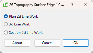
Table of Contents
Key Features
- Generates boundary edge line work from topography surfaces in a single click
- Three output modes: Plan 2D Line Work, 3D Line Work, and Section 2D Line Work
- Plan mode projects edges flat to Z=0 as 2D detail lines in the active floor plan
- 3D mode creates model lines that accurately trace the surface elevation profile
- Section mode draws 2D detail lines representing the cut profile in the active section view
- Supports both legacy
TopographySurfaceelements and the newerToposolid(Revit 2024+) - Processes multiple selected surfaces in one operation with a progress bar and cancel option
- Output is fully editable — unwanted triangulation lines can be selected and deleted after generation
Requirements
- Must be run in a project document (not a Family environment)
- One or more topography surfaces (or Toposolids) must be selected before launching the tool
- Plan 2D Line Work requires the active view to be a Floor Plan
- Section 2D Line Work requires the active view to be a Section view
- 3D Line Work can be run from any view type
Running the Tool
Launch
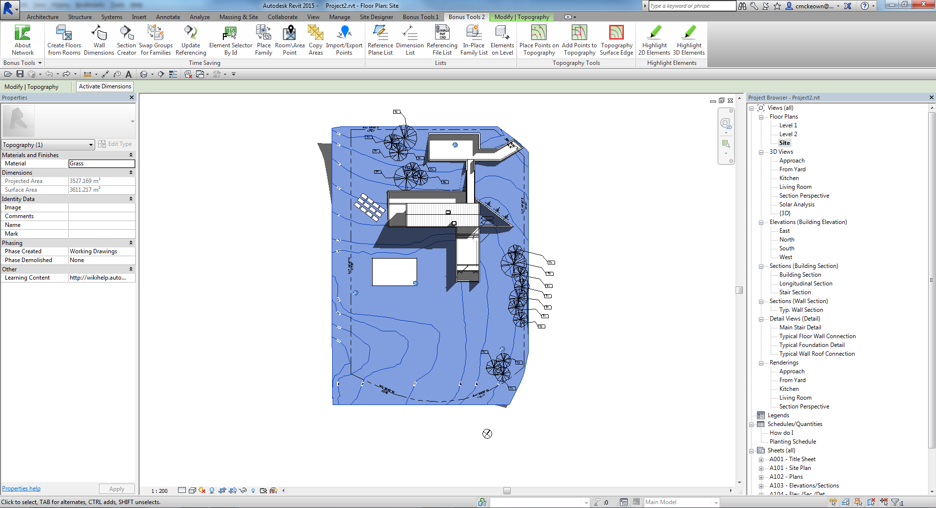
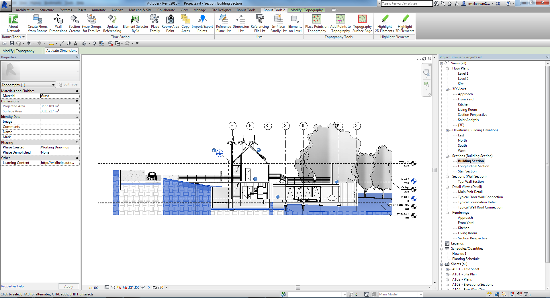
Select your topography surface(s) in the canvas first, then find Topography Surface Edge on the Bonus Tools Ribbon or use 115 Search Tools.
Select the topography surface in the project — it will highlight blue when selected.
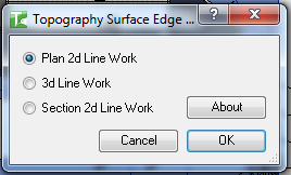
Step 1 — Choose an Output Mode
The dialog presents three mutually exclusive radio buttons. Select the mode that matches your current view and intent:
| Mode | Output | Required View |
|---|---|---|
| Plan 2D Line Work | 2D detail lines at Z=0, tracing the surface perimeter | Floor Plan |
| 3D Line Work | 3D model lines following the surface elevation | Any view |
| Section 2D Line Work | 2D detail lines showing the cut topography profile | Section |
Plan 2D Line Work is selected by default.
Step 2 — Plan 2D Result
Click OK with Plan 2D Line Work selected. The tool analyses the surface mesh and places 2D detail lines tracing the perimeter boundary, projected flat to Z=0 in the active floor plan.
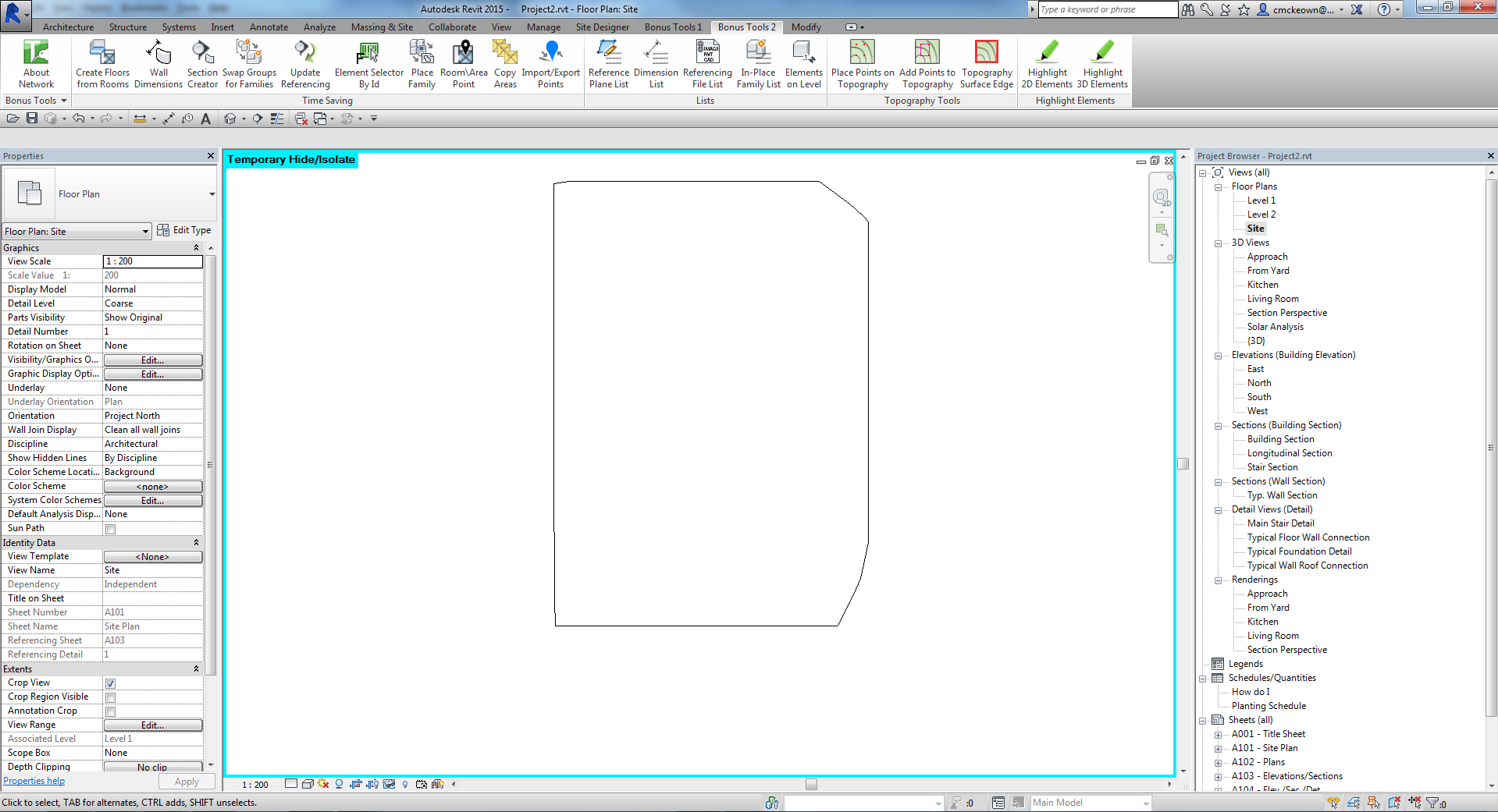
The resulting lines are standard Revit Detail Lines and can be moved, styled, or deleted like any other detail element.
Step 3 — Section 2D Result
To use Section 2D Line Work, navigate to a Section view first, then select the topography surface and run the tool.
After clicking OK, the tool generates 2D detail lines representing the full triangulated mesh as it appears cut in the section. This includes interior triangulation lines in addition to the outer profile.
Select and delete unwanted interior triangulation lines to leave only the topography surface profile. Use a Filter selection or the Tab key to isolate detail lines for faster cleanup.
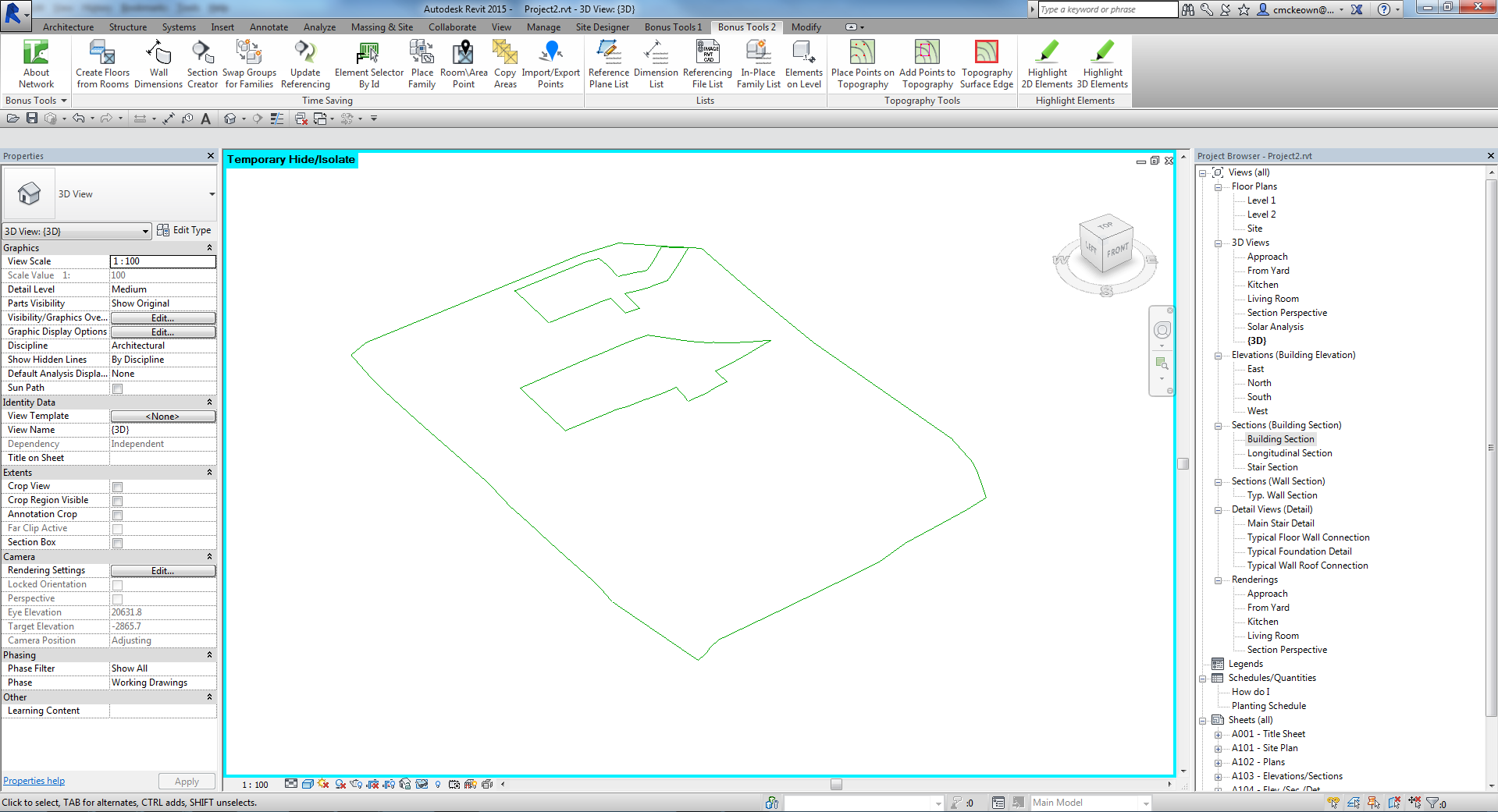
Step 4 — 3D Line Work Result
For 3D Line Work, the tool creates model lines that trace the true 3D elevation of the surface boundary. These can be viewed in any view type.
Tips and Best Practices
- Pre-select before launching — the tool reads the selection at startup; nothing is picked after the dialog opens.
- Use Plan 2D mode for site plans — the flat Z=0 projection gives a clean overhead boundary without elevation noise.
- Use 3D mode for analysis — the true-elevation model lines can be referenced in sections, elevations, and 3D views for accurate cut-and-fill visualization.
- Section mode needs cleanup — plan to spend a moment deleting interior triangulation lines after generation; the boundary profile is the outermost set of lines.
- Process multiple surfaces at once — select all relevant topography pads, roads, or sub-regions before launching to save time.
- Change line style after generation — the tool uses the default line style; select the generated lines afterwards and change their style to match your sheet standards.
- Revit 2024+ users — Toposolid elements are supported in the same way as legacy TopographySurface elements; select either type and the tool handles them identically.
Common Use Cases
Site boundary documentation Generate a clean perimeter line around the site topography in a floor plan view, then use it as the basis for a site boundary annotation or hatch region.
Section topography profile When working in a section view, run Section 2D Line Work to instantly produce a drawn topography cut profile that can be styled as a filled region or used as a reference for grading drawings.
3D site model overlay Use 3D Line Work to produce a wire-frame representation of the topography surface that can be referenced across multiple views, aiding in coordination of structure, drainage, and landscaping elements.
Locating topography in section drawings Where topography does not display clearly in a section (due to visibility settings or linked file limitations), generate section lines from the surface to explicitly show its position.
Boundary extraction for area plans Flatten the topography boundary into a floor plan and use the resulting detail lines as the starting geometry for room separation lines or site area boundaries.
Troubleshooting
"Action not available in the Family environment."
The tool can only run in a project (.rvt) file. Close the Family editor and open a project before using Topography Surface Edge.
"Please goto a plan view and try again." You selected Plan 2D Line Work but the active view is not a Floor Plan. Switch to a floor plan view before clicking OK, or choose a different output mode.
"Please goto a section view and try again." You selected Section 2D Line Work but the active view is not a Section view. Navigate to a section view first, or choose Plan 2D Line Work or 3D Line Work instead.
"No mesh found for TopographySurface .[id]" The selected element has no triangulated mesh geometry — this can happen with empty or degenerate topography surfaces. Verify the surface has points defined and is not a blank sub-region.
No lines generated after clicking OK Confirm that topography surface(s) were selected before launching the tool. If nothing was selected, the tool has no elements to process. Re-select and run again.
Too many lines in section output This is expected — the tool draws all mesh triangle edges in the cut plane. Select and delete the unwanted interior triangulation lines, leaving only the outer profile.
"Error whilst running the tool. If the problem persists please contact chris@kiwicodes.com" An unexpected error occurred. Check that the selected elements are valid topography surfaces, the view is not locked, and you have edit access to the model. Contact support if the problem persists.