020 Section Creator
Chris McKeown / July 1, 2025
Time Saving
Overview
Section Creator generates a new Revit section view through a selected wall in seconds. Select a wall, run the tool, answer two quick prompts — parallel or perpendicular, and interior or exterior — and a correctly oriented, auto-sized section view is placed in the project. The bounding box is automatically calculated from the wall's length, height, and thickness, so there is no manual crop-region adjustment needed.
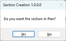
Table of Contents
Key Features
- Creates a section view through a wall with a single selection and two prompts
- Two orientation modes: parallel to the wall (wall section / elevation-style) and perpendicular to the wall (cross-section through the wall thickness)
- For parallel sections, automatically determines the correct view direction based on whether the section is interior or exterior facing, and accounts for wall flip state
- Bounding box is auto-calculated from the wall's bounding box — no manual crop adjustment required
- Parallel section offset is scaled to 2× the wall thickness so reveals and adjacent elements are always visible
- Perpendicular section depth is fixed at 5 ft / 1.5 m past the wall face — enough to show adjacent construction
- Uses the first available Section view family type in the project, so it respects your project's view templates and graphic settings
- Works in any project file; blocked in Family documents
Requirements
- Exactly one wall must be selected before running the tool
- The wall must have a straight (linear) location curve — arc walls are not supported for the parallel orientation
- Must be run in a project file (not a Family document)
- The project must contain at least one Section view family type
Running the Tool
Launch
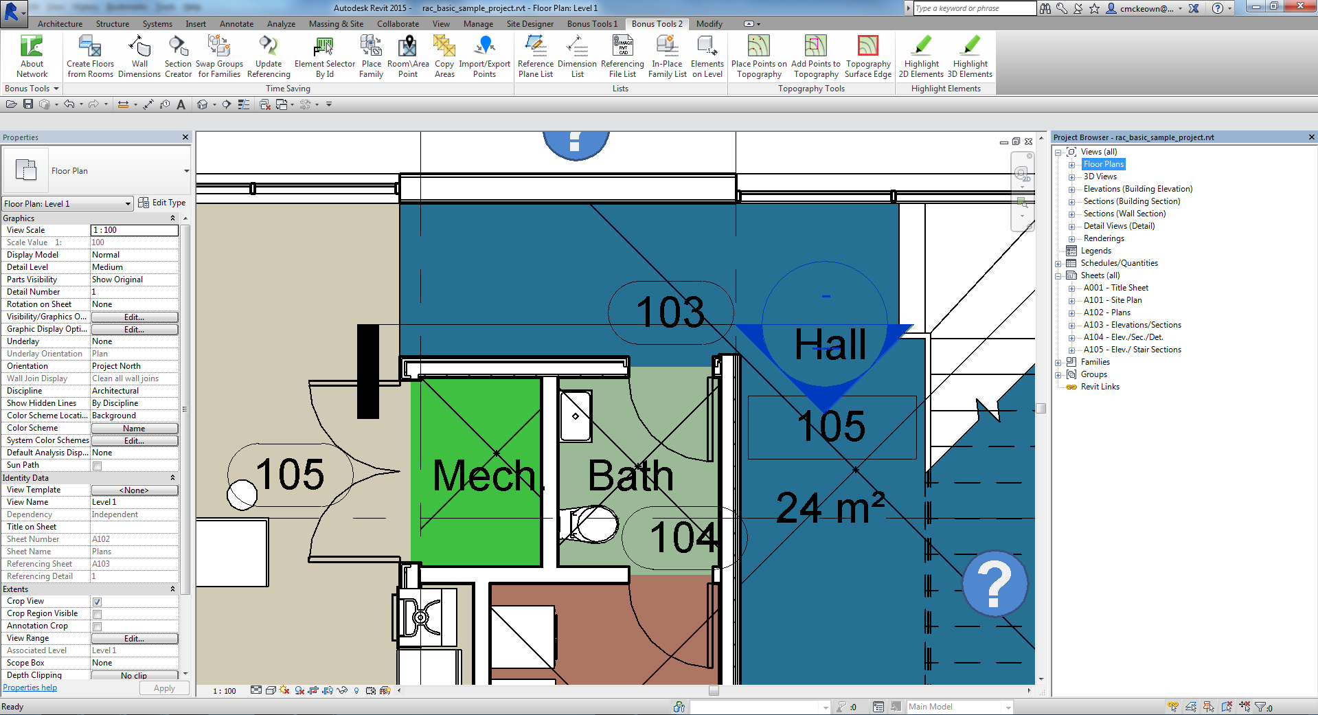
Select a wall in the project, then find Section Creator on the Bonus Tools Ribbon or use 115 Search Tools.
Important: The wall selection must be made before launching the tool. If no wall (or more than one element) is selected when the command runs, it will return an error prompt and exit without creating a view.

Step 1 — Choose the Section Orientation
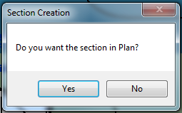
A dialog asks: "Do you want the section in Plan?"
- Yes — creates a section view parallel to the wall face (looking along the wall, as you would see in an elevation or wall section). This mode also asks a second question about interior vs. exterior facing.
- No — creates a section view perpendicular to the wall (cutting through the wall thickness, as you would see in a typical building section or detail).
Step 2 — Specify Interior or Exterior (Parallel sections only)
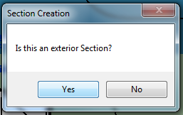
If you chose Yes (parallel / plan section) in Step 1, a second dialog asks: "Is this an exterior Section?"
- Yes — the view looks from the outside of the building toward the wall face. The tool reads the wall's flip state and sets the view direction so that the exterior face is the near face in the view.
- No — the view looks from the inside, showing the interior face of the wall as the near face.
This step does not appear for perpendicular sections.
Step 3 — Review the Generated Section
The tool creates the section view inside a "New Section" transaction and places it in the Project Browser under the Section view family type used. Open it from the Project Browser or from the section head that appears in plan.
The crop region is pre-set — for parallel sections it extends 60% of the wall length on each side of the midpoint, and for perpendicular sections it spans 2× the wall thickness on each side, from base to top with a 1 ft margin above and below.
Tips and Best Practices
- Pre-select the wall before running the tool. The command reads the selection at launch — there is no in-tool selection step.
- Use perpendicular sections for construction details. The 5 ft section depth captures enough of the adjacent floor and ceiling construction to build a useful detail.
- Use parallel (plan) sections for wall elevations. These produce a view looking straight at a wall face, ideal for tile layouts, cladding elevations, or room interior elevations.
- Check wall flip before using parallel/exterior. If the generated section faces the wrong way, undo, flip the wall in plan (
Spacebarwhile selected), and run the tool again, or simply adjust the section crop region manually. - Rename the view immediately. The tool creates the section with a default Revit name. Rename it in the Project Browser right after creation to keep the project organised.
- Apply a view template after creation. The section is created without a view template. Assign one from the Properties panel to apply the correct line weights and visibility settings.
- The section head appears in the active view. After creation, look at the current plan view — the section marker is placed there. Drag it if needed to avoid cluttering the drawing.
Common Use Cases
Wall section for documentation — Select a key structural or façade wall, run the tool with the perpendicular option, and instantly have a cross-section positioned correctly through that wall ready to develop into a construction detail.
Interior room elevation — Select a wall bounding a room, choose the parallel/plan option, and answer "No" (interior) to get an elevation looking at the internal face of that wall. Useful for setting out wall tiles, joinery, or feature walls.
Exterior façade elevation — Select an external wall, choose parallel, and answer "Yes" (exterior) to generate a view looking at the building face. Useful for cladding set-out or façade annotation.
Rapid section placement across multiple walls — Work through each wall in sequence: select, run tool, accept defaults. Each run creates a new section, so you can quickly build up a full set of wall sections across a floor plate without manually placing section markers.
Quality checking wall construction — Use the perpendicular option on walls at junctions or corners to verify that the wall layers, offsets, and connections are modelled correctly before issuing for construction.
Troubleshooting
"Please select exactly one wall element." The tool exited without opening any dialog. Either no elements were selected, more than one element was selected, or the selected element was not a wall. Deselect everything, click a single wall, then run the tool again.
"Action not available in the Family environment." The tool was run while a Family file was open and active. Close the Family editor, switch to a project document, and try again.
"Unable to retrieve wall location line." The selected wall does not have a straight (linear) location curve. Curved or arc walls are not supported for the parallel section orientation. Use the perpendicular orientation instead, or use a straight wall segment.
Section is created but faces the wrong direction This can happen with parallel sections if the wall's interior/exterior flip state is the reverse of what you expected. Undo the section, check the wall's flip orientation in plan (the interior face indicator should face the correct side), then rerun the tool with the same orientation and interior/exterior answer. Alternatively, open the section view and manually mirror the crop region.
Section view is not visible in the Project Browser The section was created but may be nested inside a group in the Browser. Scroll to the Section category in the Project Browser, expand it, and look for a view named with Revit's default section numbering (e.g., "Section 1"). Use 115 Search Tools to locate it by name if the Browser is deeply nested.
Crop region seems too small or too large The crop is sized automatically from the wall's bounding box and thickness. For very thin or very thick walls the offsets may not suit the detail level required. Adjust the crop region manually in the section view after creation — unlock the crop, drag the boundary handles, and re-lock.