143 Convert DWGs
Chris McKeown / July 1, 2025
Time Saving
143 Convert DWGs
Overview
The Convert DWGs tool converts linked CAD (DWG/DXF) files into native Revit linework, either directly in the project or as loadable families. It analyzes all layers in the linked CAD file, allows you to map each layer to a Revit line style, then creates corresponding detail lines, model lines, or boundary lines. This eliminates the need for linked CAD files in your project while maintaining the graphic information, improving performance and enabling full Revit control over linework.
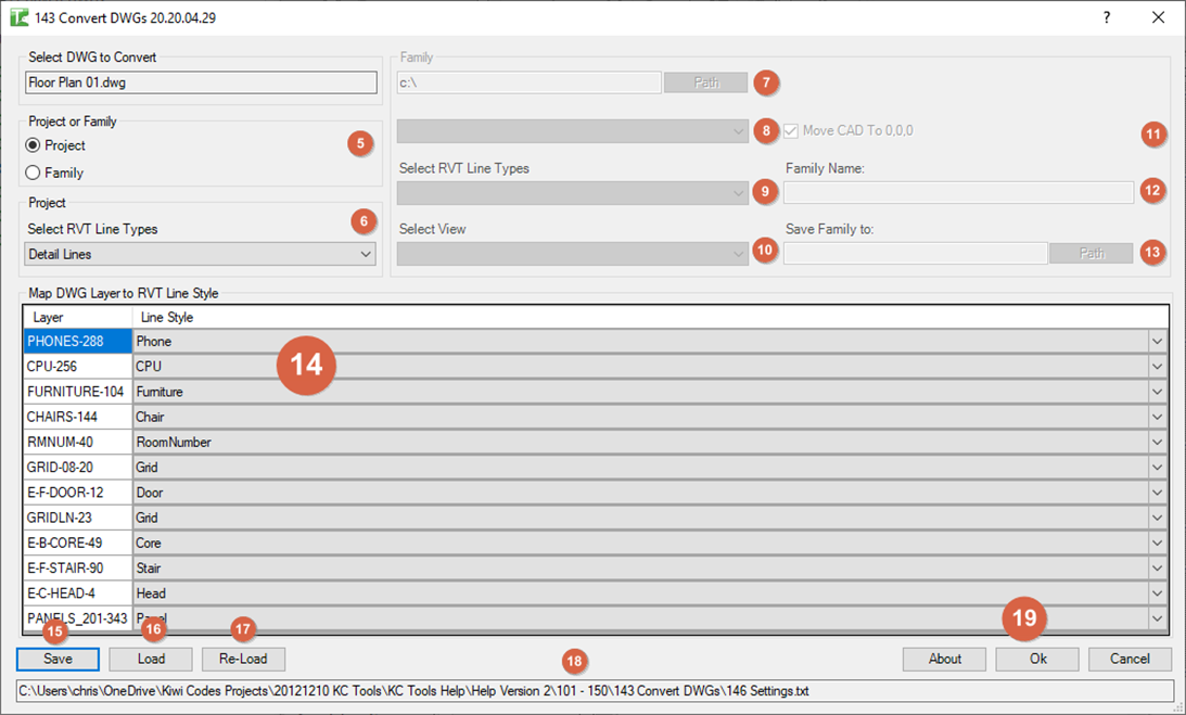
Table of Contents
- Key Features
- Requirements
- Interface Guide
- Step-by-Step Guide
- Understanding Layer Mapping
- Example Workflows
- Tips and Best Practices
- Common Use Cases
- Troubleshooting
Key Features
- Converts linked CAD files to native Revit linework
- Two conversion modes: Project lines or Loadable Family
- Supports multiple line types:
- Detail Lines (annotation)
- Model Lines (3D geometry)
- Area Boundary Lines
- Room Separation Lines
- Space Separation Lines
- Layer-by-layer mapping to Revit line styles
- Visual layer list with element counts
- Save and load layer mapping configurations
- Progress indicators for large conversions
- Family creation with template selection
- Option to move CAD to origin before conversion
- Batch processing of all mapped layers
- Preserves CAD geometry accurately
- Handles polylines and complex curves
Requirements
Pre-requisites
-
Linked CAD File
- DWG or DXF must be linked (not imported) in project
- Link must be selected before opening tool
- CAD file should be in current view
- Link must contain valid geometry
-
Appropriate View Type
- Detail/Model lines: Any view type
- Area Boundaries: Area Plan view required
- Room Separation: Floor Plan view required
- Space Separation: Floor Plan view required
-
Line Styles in Project
- Project must have line styles defined
- Default Revit line styles available
- Custom line styles optional
- Family mode requires family line styles
-
For Family Mode
- Family template files accessible
- Valid output directory for saving families
- Write permissions to output folder
Recommended Setup
Before Using Tool:
- Link CAD file into project
- Select the CAD link in a view
- Ensure view is appropriate for line type
- Create or verify line styles exist
- For family mode, locate family template folder
Interface Guide
Select DWG to Convert
DWG Name Field (Read-only):
- Displays name of selected CAD link
- Automatically populated when tool opens
- Shows category name from Revit
- Cannot be edited
Project or Family Mode
○ Project (Default)
- Converts CAD to lines directly in current project
- Lines created in active view
- Uses project line styles
- Immediate results
○ Family
- Creates new loadable family containing CAD linework
- Family saved to specified location
- Loaded back into project after creation
- Uses family line styles
Project Settings (Project Mode)
Select RVT Line Types Dropdown:
- Detail Lines: Annotation lines (view-specific)
- Model Lines: 3D model geometry
<Area Boundary>: Area plan boundary lines<Room Separation>: Room boundary lines<Space Separation>: Space boundary lines
Behavior:
- Changes available line styles in mapping grid
- Validates view type compatibility
- Filters inappropriate line types
Family Settings (Family Mode)
Family Template Path:
- Path to folder containing family templates (.rft files)
- Click Path button to browse
- Dropdown populates with available templates
- Default:
C:\
Select RVT Line Types Dropdown:
- Detail Lines: Annotation lines in family
- Model Lines: Model geometry in family
Select View Dropdown:
- Lists views available in selected template
- Determines which view receives linework
- Populated after template selection
Move CAD To 0,0,0 Checkbox:
- ✓ Moves CAD to origin before conversion
- Useful for families requiring origin placement
- Adjusts geometry during conversion
Family Name:
- Name for created family file
- Required field
- Invalid characters replaced with underscores
- Extension (.rfa) added automatically
Save Family to:
- Output directory for family file
- Click Path button to browse
- Must have write permissions
- Default:
C:\
Map DWG Layer to RVT Line Style (Grid)
Layer Column (Read-only):
- Lists all CAD layers found in link
- Format:
LayerName-Count - Count shows number of geometry objects
- Sorted alphabetically
- Cannot be edited
Line Style Column (Dropdown):
- Selects Revit line style for this layer
- Options change based on line type selection
- Empty = layer will be skipped
- Auto-opens dropdown on cell entry
Grid Features:
- One row per CAD layer
- Only mapped layers (with line style) are converted
- Unmapped layers are ignored
- Can map multiple layers to same line style
Action Buttons
Save
- Exports current layer mapping to text file
- Saves layer names and assigned line styles
- Can be reloaded later
- Format: CSV text file
Load
- Imports previously saved layer mapping
- Updates line style assignments
- Matches layers by name
- Skips layers not in current CAD
Re-Load
- Refreshes mapping from currently specified file
- Re-applies saved settings
- Useful after changing line type selection
About
- Displays tool version and information
Ok
- Executes CAD conversion
- Processes all mapped layers
- Shows progress bar during conversion
- Displays completion message
Cancel
- Closes dialog without converting
- No changes made to project
Step-by-Step Guide
Basic Project Conversion
-
Link and Select CAD File
- In Revit: Insert → Link CAD
- Browse to DWG/DXF file
- Link file into current view
- Select the linked CAD instance
-
Open the Tool
- With CAD link selected
- Navigate to Bonus Tools tab
- Click 143 Convert DWGs
- Dialog opens with CAD name displayed
-
Choose Project Mode
- Verify Project radio button selected
- This is the default mode
- Creates lines directly in project
-
Select Line Type
- Choose from Select RVT Line Types dropdown
- For typical details: "Detail Lines"
- For 3D content: "Model Lines"
- For boundaries: appropriate boundary type
-
Map Layers to Line Styles
- Review layer list in grid
- Click Line Style cell for each layer
- Select appropriate Revit line style
- Leave blank to skip unwanted layers
-
Save Mapping (Optional)
- Click Save button
- Choose location and filename
- Save for reuse on similar CAD files
-
Execute Conversion
- Click Ok button
- Progress bar displays during processing
- Wait for completion message
- Review created linework in view
-
Verify Results
- Check created lines in view
- Verify line styles applied correctly
- Delete CAD link if satisfied
- Clean up any conversion issues
Creating Family from CAD
-
Prepare CAD Link
- Link CAD file into project
- Select the CAD link
- Note its current position
-
Open Tool in Family Mode
- Open 143 Convert DWGs
- Select Family radio button
- Family settings panel enables
-
Select Family Template
- Click Path button for template folder
- Browse to Revit family template location
- Common:
C:\ProgramData\Autodesk\RVT [version]\Family Templates\ - Select template dropdown populates
-
Choose Template
- Select template from dropdown
- Example: "Generic Model.rft"
- View dropdown populates with template views
-
Configure Family Settings
- Select RVT Line Types: Choose Detail or Model
- Select View: Choose view for linework
- Move CAD To 0,0,0: Check if needed
- Family Name: Enter descriptive name
- Save Family to: Browse to output folder
-
Map Layers
- Line Style dropdown shows family line styles
- Map CAD layers to family line styles
- Note: Different line styles than project
-
Create Family
- Click Ok
- Tool creates family document
- Converts CAD linework
- Saves family file
- Loads family into project
- Places instance at origin
-
Review Family
- Check placed family instance
- Edit family to review linework
- Adjust as needed
- Family saved to specified location
Loading Saved Mapping
-
Open Tool with CAD Selected
- Select linked CAD file
- Open Convert DWGs tool
-
Locate Mapping File
- Click Load button
- Browse to previously saved mapping file
- Select text file
- Click Open
-
Review Applied Mapping
- Tool automatically maps layers
- Line styles assigned based on file
- Unmapped layers remain blank
- Can manually adjust as needed
-
Convert with Loaded Settings
- Verify mappings correct
- Click Ok to convert
- Same settings as previous conversion
Converting Specific Layer Types
Detail Lines Conversion:
- Select Detail Lines from line type dropdown
- Map CAD layers to detail line styles
- Lines created as view-specific annotation
- Useful for: Sections, details, schedules
Model Lines Conversion:
- Select Model Lines from line type dropdown
- Requires sketch plane in current view
- Map layers to model line styles
- Creates 3D geometry
- Useful for: 3D layouts, massing studies
Room Separation Conversion:
- Open Floor Plan view
- Select
<Room Separation>from dropdown - Note: Only this option available in dropdown
- Map layers to create room boundaries
- Lines appear as room boundary lines
- Useful for: Converting CAD space plans
Area Boundary Conversion:
- Open Area Plan view
- Select
<Area Boundary>from dropdown - Map layers for area boundaries
- Creates area boundary lines
- Useful for: Rentable/usable area analysis
Understanding Layer Mapping
Layer List Format
Display Format: LayerName-Count
Example:
A-WALL-100
A-DOOR-25
A-WIND-18
S-GRID-10
Components:
- LayerName: Original CAD layer name
- Count: Number of geometry objects on layer
- Includes individual line segments from polylines
- Higher count = more geometry
Sorting:
- Alphabetically by layer name
- Same as CAD layer organization
- Easy to find specific layers
Line Style Selection
Available Line Styles Depend On Mode:
Project Detail Lines:
- All project detail line styles
- Example: Thin Lines, Medium Lines, Wide Lines
- Custom project line styles included
- Excludes: <Sketch>, <Fabric Sheets>, boundary types
Project Model Lines:
- All project model line styles
- Same as detail lines but for model category
- Creates 3D geometry
Boundary Lines:
- Only single boundary type available
- Area:
<Area Boundary> - Room:
<Room Separation> - Space:
<Space Separation>
Family Lines:
- Line styles from family template
- Includes family category style
- Sub-categories of family category
- Different from project line styles
Mapping Strategy
Unmapped Layers:
- Leave Line Style dropdown empty
- Layer will be skipped during conversion
- No error—intentional filtering
- Useful for excluding unwanted layers
Multiple Layers to One Style:
- Can map different CAD layers to same line style
- All merge into single Revit line style
- Useful for standardizing varied CAD layers
- Example: Map "A-WALL", "A-WALL-EXT", "A-WALL-INT" all to "Wide Lines"
One-to-One Mapping:
- Each CAD layer to unique Revit line style
- Maintains CAD layer distinction
- Requires sufficient Revit line styles
- May need to create custom line styles
Saving Mapping Files
File Format: Plain text CSV
Contents:
Layer / Linetype export - DWG to RVT
A-WALL-100, Wide Lines
A-DOOR-25, Medium Lines
A-WIND-18, Medium Lines
S-GRID-10, Thin Lines
First Line: Header (ignored on load)
Subsequent Lines: LayerName-Count, Line Style Name
Loading Behavior:
- Matches by layer name (ignores count)
- Applies line style if it exists in current mode
- Skips layers not found in current CAD
- Skips line styles not available
- Special handling for boundary line types
Example Workflows
Workflow 1: Converting Architectural Detail
Scenario: CAD detail section to Revit drafting view
-
Prepare Revit View
- Create new Drafting View
- Name: "Wall Section Detail"
- Scale: 3/4" = 1'-0"
-
Link CAD File
- Link detail DWG into drafting view
- Position appropriately
- Select linked CAD
-
Configure Conversion
- Open Convert DWGs tool
- Mode: Project
- Line Type: Detail Lines
-
Map Layers Intelligently
- Heavy lines (A-WALL, S-CONC): "Wide Lines"
- Medium lines (A-DOOR, A-WIND): "Medium Lines"
- Light lines (A-DIMS, A-NOTES): "Thin Lines"
- Hidden lines (A-HIDDEN): "Hidden Lines"
- Skip dimension/text layers (will add Revit annotations)
-
Save Mapping
- Save as "Architectural_Detail_Mapping.txt"
- Reuse for similar details
-
Convert
- Click Ok
- Wait for completion
- Review 100-200 lines created
-
Post-Conversion Cleanup
- Delete CAD link
- Add Revit dimensions and text
- Adjust line styles if needed
- Place on sheet
Result: Native Revit detail with full editing capability
Workflow 2: Creating Family from CAD Block
Scenario: Furniture CAD block to Revit family
-
Link CAD Block
- Link furniture DWG
- In floor plan view
- Select link
-
Configure Family Creation
- Mode: Family
- Template path: Browse to templates
- Template: "Furniture.rft"
- View: "Ref. Level" or "Front"
- Line Type: Model Lines
-
Enable CAD Centering
- ✓ Move CAD To 0,0,0
- Ensures family centered at origin
-
Set Output
- Family Name: "Office Chair - CAD Conversion"
- Save to: Project furniture library folder
-
Map Layers
- Map all visible layers to family line styles
- Skip hidden or construction layers
-
Create and Load
- Click Ok
- Family created and loaded
- Instance placed at 0,0,0
-
Refine Family
- Edit family
- Add parameters if needed
- Assign category
- Add 3D geometry or keep 2D
- Save and reload
Result: Reusable furniture family from CAD
Workflow 3: Room Boundary Conversion
Scenario: CAD space plan to Revit room layout
-
Prepare Floor Plan
- Open architectural floor plan
- Ensure at correct level
- Link CAD space plan
-
Configure for Rooms
- Select CAD link
- Open tool
- Mode: Project
- Line Type:
<Room Separation>
-
Map Room Boundary Layers
- Identify CAD layers representing walls/partitions
- Map these to room separation
- Skip furniture, equipment layers
- Only mapped layers become boundaries
-
Convert
- Click Ok
- Room separation lines created
- Verify closed room boundaries
-
Create Rooms
- Architecture → Room
- Place rooms in defined spaces
- Rooms automatically bound by separation lines
-
Clean Up
- Delete CAD link
- Adjust room separation lines if needed
- Add room tags
Result: Revit rooms matching CAD space plan
Workflow 4: Multi-Detail Conversion with Saved Mapping
Scenario: Convert multiple similar CAD details using same mapping
-
Convert First Detail
- Link first CAD detail
- Select and open tool
- Map layers thoughtfully
- Save mapping as "Standard_Detail_Mapping.txt"
- Convert detail
-
Prepare Second Detail
- Create new drafting view
- Link second CAD detail
- Select link
-
Load Saved Mapping
- Open Convert DWGs tool
- Click Load
- Select "Standard_Detail_Mapping.txt"
- Mappings applied automatically
-
Adjust if Needed
- Review applied mappings
- Adjust any layers unique to this detail
- Most mappings should be correct
-
Convert
- Click Ok
- Detail converted with standard settings
-
Repeat for Remaining Details
- Link each CAD file
- Load same mapping
- Quick conversions with consistency
Result: Multiple details with consistent line style application
Workflow 5: Area Boundary Setup
Scenario: Creating departmental area plan from CAD
-
Create Area Plan
- Architecture → Area and Volume Computations
- Create Area Scheme: "Departments"
- Create Area Plan view
-
Link CAD File
- Link departmental CAD drawing
- In area plan view
- Select link
-
Configure Conversion
- Mode: Project
- Line Type:
<Area Boundary> - Only option:
<Area Boundary>
-
Map Department Boundary Layers
- Identify CAD layers showing department boundaries
- Map to area boundary
- Skip non-boundary layers
-
Convert
- Creates area boundary lines
- Defines area extents
-
Place Areas
- Architecture → Area
- Place in each department
- Areas bound by converted boundaries
- Tag areas
Result: Area plan ready for calculation and schedules
Tips and Best Practices
-
Always Save Mappings for Reuse
- First conversion takes time to map
- Saved mappings make future conversions instant
- Organize mapping files by CAD type/source
- Include in project templates
-
Test on Small Section First
- Link full CAD file
- Map and convert just few important layers
- Verify result before mapping all layers
- Easier to troubleshoot issues
-
Consider Line Weight Strategy
- Match CAD line weights to Revit line styles
- Heavy CAD lines → Wide Revit lines
- Light CAD lines → Thin Revit lines
- Maintains visual hierarchy
-
Skip Unnecessary Layers
- Don't map layers you won't use
- Examples: Text, dimensions, hatching (add natively in Revit)
- Defpoints, metadata layers
- Reduces conversion time
-
Use Appropriate Line Type
- Details and sections: Detail Lines
- Plans requiring 3D: Model Lines
- Space planning: Room/Area boundaries
- Affects downstream usage
-
Delete CAD Link After Conversion
- Once satisfied with conversion
- Improves file performance
- Forces use of native Revit tools
- Keep original CAD archived externally
-
Large CAD Files Take Time
- Files with thousands of lines may take 10-30 minutes
- Progress bar shows status
- Can cancel if needed
- Consider converting in phases
-
Family Mode for Reusable Content
- Equipment, furniture, symbols
- Standard details to reuse
- Allows parametric enhancement later
- Organized family library
-
Verify View Type Before Starting
- Area boundaries require area plan
- Room/space separations require floor plan
- Model lines require sketch plane
- Tool validates but prevents errors
-
Document Your Mapping Logic
- Note why certain layers mapped to certain styles
- Include in BIM execution plan
- Helps team understand conversions
- Maintains project standards
Common Use Cases
CAD Detail Conversion
Purpose: Convert legacy CAD details to native Revit
Approach:
- Create drafting views for each detail
- Link CAD details
- Create standard layer mapping
- Convert all details using saved mapping
- Delete CAD links
- Add Revit annotations
Benefits:
- Native Revit details
- Editable line work
- Better performance
- Integrated with project
Site Plan Conversion
Purpose: Convert civil CAD site plan to Revit model
Approach:
- Link site CAD in site plan view
- Use model lines for 3D elements
- Map property lines, roads, contours
- Convert to Revit model lines
- Add Revit topography
- Enhance with Revit site tools
Benefits:
- 3D site model
- Coordination with building
- Better visualization
- Revit site tools available
Equipment Family Library
Purpose: Build library of equipment families from CAD blocks
Approach:
- Collect CAD equipment blocks
- Convert each to family using family mode
- Use appropriate templates
- Center CAD at origin
- Create family library structure
- Load into project as needed
Benefits:
- Consistent equipment families
- Leverages existing CAD assets
- Faster than redrawing
- Parametric enhancement possible
Space Planning Import
Purpose: Import client CAD space plan into Revit
Approach:
- Link space plan CAD
- Convert to room separations
- Create rooms from boundaries
- Add room tags and schedules
- Validate areas against program
- Develop design from space plan
Benefits:
- Quick space plan setup
- Accurate to client requirements
- Room-based workflow
- Area calculations immediate
As-Built Conversion
Purpose: Convert as-built CAD drawings to Revit
Approach:
- Link as-built CAD files
- Convert to detail/model lines as appropriate
- Use as reference for modeling
- Gradually replace CAD with native Revit elements
- Keep converted lines as backup reference
- Eventually remove all CAD references
Benefits:
- Accurate existing conditions
- Reference for modeling
- Verification of model accuracy
- Historical record
Troubleshooting
"Could not create lines in the current view"
Problem: Conversion completes but no lines created
Solutions:
- View type incompatible with line type:
- Area boundaries require area plan view
- Room/space boundaries require floor plan
- Check active view type
- No layers mapped: All line style cells empty
- Map at least one layer
- Check mapping loaded correctly
- CAD link has no geometry: Empty or corrupt CAD
- Verify CAD file opens in AutoCAD
- Check layer list has counts > 0
- Sketch plane missing (model lines):
- Ensure view has work plane
- Set work plane before converting
Layer List Is Empty
Problem: Grid shows no layers
Solutions:
- CAD link may be empty
- CAD file might not be truly linked
- Geometry not in link's geometry
- Try relinking CAD file
- Verify CAD file has content in AutoCAD
- Check CAD file not corrupted
Line Styles Don't Appear in Dropdown
Problem: Line Style dropdown is empty or missing styles
Solutions:
- Line type selection affects available styles
- Change between Detail/Model/Boundary modes
- For boundaries, only boundary style available
- In family mode, family template determines styles
- Create custom line styles if needed
- Check project has line styles defined
Conversion Takes Extremely Long
Problem: Progress bar barely moving, hours to complete
Solutions:
- Very large CAD file (>10MB, >10,000 objects)
- Unmap layers with huge counts to reduce load
- Convert in phases (subsets of layers)
- Can cancel with progress bar and retry smaller
- Some complex polylines slow processing
- Consider simplifying CAD in AutoCAD first
Mapping File Won't Load
Problem: Loaded mapping doesn't apply to layers
Solutions:
- Layer names must match exactly
- Check for extra spaces or characters
- CAD may have different layers than mapping file
- Line styles in mapping may not exist in current mode
- Example: Project mapping loaded in family mode
- Verify mapping file format correct
- Try manually setting few layers to test
Family Creation Fails
Problem: Error during family creation or load
Solutions:
- Template file not found:
- Verify template path correct
- Check template dropdown has selection
- Browse to valid Revit template folder
- Output directory invalid:
- Check save family path exists
- Verify write permissions
- Try saving to desktop instead
- Family name invalid:
- Tool replaces illegal characters automatically
- Check for very long names (>250 characters)
- Template incompatible:
- Use appropriate template for line type
- Detail lines work in most templates
- Model lines may require specific templates
Lines Created in Wrong Location
Problem: Converted lines not where CAD link was
Solutions:
- CAD link position affects line placement
- Lines created at CAD geometry coordinates
- In family mode: Use "Move CAD To 0,0,0" option
- In project: CAD link position is reference
- Reposition CAD link before converting
- Can move lines after conversion with normal tools
Some Layers Don't Convert
Problem: Specific layers skipped despite mapping
Solutions:
- Check layer count in layer list
- Count = 0 means no geometry on layer
- Verify line style actually selected (not blank)
- Some CAD geometry types may not convert:
- Text (not geometry)
- Hatches (not lines)
- Blocks/inserts (nested geometry)
- 3D geometry in 2D view
- Check CAD layer not frozen/off in original file
Line Styles Don't Match Expectations
Problem: Converted lines have wrong appearance
Solutions:
- Verify correct line style selected in mapping
- Check Revit line style definition:
- Manage → Object Styles → Annotation/Model Objects
- Review line style weight, color, pattern
- Line style might be view-specific override
- Check view's Visibility/Graphics overrides
- May need to adjust Revit line styles to match CAD
Polylines Convert as Individual Segments
Problem: Continuous CAD polylines become separate Revit lines
Solutions:
- This is expected behavior
- Revit doesn't have true polyline element
- Each segment becomes individual line
- Can join lines in Revit if needed:
- Select lines → Modify tab → Join
- Affects selection and modification workflow
- Consider if issue for your use case
Progress Bar Freezes
Problem: Progress bar stops updating
Solutions:
- May not be frozen—very slow operation
- Large complex geometry takes time per element
- Wait at least 10-15 minutes before canceling
- Watch Revit status bar for activity
- Check Task Manager—is Revit responding?
- If truly frozen, force close and retry with fewer layers
Lines Created But CAD Still Visible
Problem: Both Revit lines and CAD link showing
Solutions:
- This is normal—CAD link not automatically hidden
- Tool doesn't delete CAD link
- Manually hide or delete CAD link:
- Select CAD link
- Delete key or Hide in View
- Compare conversion quality before deleting CAD
- Keep CAD link hidden as backup initially
Family Doesn't Load Into Project
Problem: Family created but not appearing in project
Solutions:
- Check if family actually saved to output folder
- Family may have loaded but not placed
- Check Project Browser → Families
- Error during family load:
- Check family file not corrupt
- Try manually loading family
- File → Load Family → Browse to created family
- Instance placement may have failed
- Tool tries to place at origin
- Look for instance at 0,0,0
- Manually place family symbol if needed
Need Help? Contact support or refer to additional Bonus Tools documentation.
Thank you for using Bonus Tools - Convert DWGs!