117 3D Selection Box
Chris McKeown / July 1, 2025
3D Views
Overview
3D Selection Box lets you draw a rectangular crossing box directly in a Revit view, then automatically creates and activates a new isometric 3D view scoped to that box. The section box is sized to the area you draw, with a 500 mm margin added below and 3000 mm added above to ensure the model content within the area is fully captured. It is a fast alternative to manually creating a 3D view and adjusting the section box by hand.
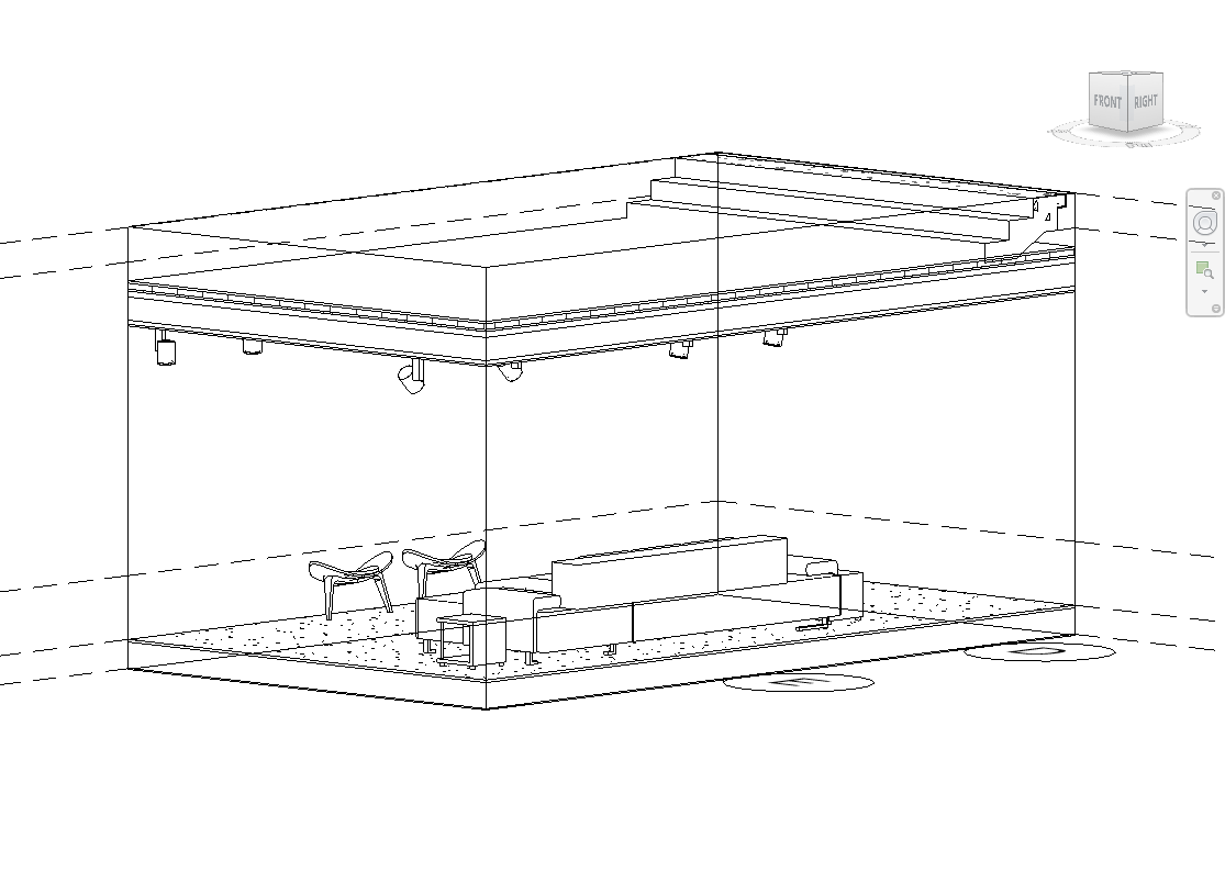
Table of Contents
Key Features
- Draw any crossing box directly in the current view — no dialog required
- Instantly creates a new isometric 3D view scoped to the drawn area
- Section box margins: 500 mm below the box minimum Z, 3000 mm above the box maximum Z
- Automatically activates the new 3D view so you see the result immediately
- Works from any view type where box selection is available
- Uses the project's first available ThreeDimensional View Family Type
- Creates a standard Revit isometric 3D view — can be renamed, duplicated, and used like any other 3D view
Requirements
- Must be run from a Revit project document — not available in the Family Editor
- At least one ThreeDimensional View Family Type must exist in the project (present in all standard Revit templates)
Running the Tool
Launch
Find 3D Selection Box on the Bonus Tools Ribbon or use 115 Search Tools.
The Revit cursor switches to box-selection mode immediately — no dialog opens.
Step 1 — Draw the Selection Box
Click and drag to draw a rectangular crossing box over the area of the model you want to view in 3D. The box can be drawn in any plan, elevation, section, or 3D view.

Draw the box to include the full plan footprint of the area you want — the section box will be automatically extended vertically.
Step 2 — New 3D View Opens Automatically
As soon as you release the mouse, the tool:
- Calculates the bounding box from your selection (using the box Min and Max XYZ)
- Expands the bounding box by 500 mm below (Z minimum) and 3000 mm above (Z maximum)
- Creates a new isometric 3D view and applies this as the section box
- Sets the new 3D view as the active view

The section box vertical extents are calculated using the project units so the 500 mm / 3000 mm margins are accurate regardless of the unit system in use.
Step 3 — Rename and Organise (Optional)
The new 3D view is created with a default Revit name. Rename it in the Project Browser to something meaningful if you intend to keep and reuse the view.
Each run of the tool creates a new 3D view. If you run the tool multiple times, multiple views are created. Delete any unused views to keep the Project Browser clean.
Tips and Best Practices
- Draw generously. Include a slightly larger area than strictly needed — the section box can always be adjusted further in the 3D view after creation using the standard Revit section box grips.
- Use in a plan view for the most predictable result. Drawing the box in a floor plan gives an accurate horizontal footprint. The 500 mm / 3000 mm vertical margins handle typical storey heights — for multi-storey selections, adjust the section box manually after creation.
- Rename created views immediately. Revit assigns a generic name to each new view. Rename it straight away if you plan to use it on a sheet or share it with the team.
- Adjust the section box after creation. The created view is a standard Revit 3D view with a section box — select the section box in the 3D view and drag its grips to refine the extents without re-running the tool.
- Delete unwanted views. Each tool run creates a new view. Delete any exploratory views you no longer need to avoid cluttering the Project Browser.
Common Use Cases
Quick coordination view — Draw a box around a specific area (e.g. a structural connection, MEP clash, or stairwell) to instantly get a 3D view focused on that area for coordination or clash review.
Scoping a 3D view for a detail sheet — Draw the box around a building corner or specific element to create a 3D view sized for a detail sheet, then apply a view template and rename.
Isolating a single room or zone — Draw the box over a room boundary in a plan view to produce a 3D view that shows only that room's content, without manually editing the section box.
Reviewing model content in a specific area — After receiving an updated linked model, draw a box over the changed area to quickly inspect the 3D content without adjusting an existing view's section box.
Troubleshooting
Tool is not available (greyed out) 3D Selection Box cannot run in a Family Document. Open a project file and try again.
A new 3D view is created but the section box appears too large or too small The vertical margins are fixed at 500 mm below and 3000 mm above the drawn box extents. For multi-storey areas or very tall spaces, manually adjust the section box grips in the new 3D view after creation.
Pressing Escape cancels the tool If you press Escape during the box-selection step, the tool exits without creating a view. Run the tool again to try another selection.
Multiple unwanted 3D views accumulating in the project Each run creates a new view. Delete any views you no longer need via the Project Browser to keep the file organised.
"Action not available in the Family environment." Open a Revit project document instead of a family file and try again.