011 3D View for Selected Elements
Chris McKeown / July 1, 2025
Sheet & View Manipulation
Overview
3D View for Selected Elements creates an isometric 3D view with a section box fitted to the bounding box of all currently selected Revit elements, expanded by a configurable margin on all sides. Use it to instantly isolate any set of elements in 3D for inspection, coordination, or documentation — without manually setting up a view or adjusting a section box. Assigning a keyboard shortcut makes this one of the fastest inspection tools in the workflow.
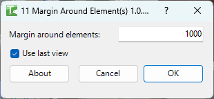
Table of Contents
Key Features
- Computes a precise bounding box around all selected elements and expands it by a user-specified margin
- Offset field — margin in project units applied equally to all six sides of the bounding box
- Use Last View checkbox — updates the previously generated view instead of creating a new one, preventing Project Browser clutter
- View opens automatically after creation for immediate inspection
- Works with any mix of element categories and types in the selection
- Transaction: "Create view"
- Confirmation: green success message with the view name
Requirements
- One or more Revit elements must be selected before running the tool
- A valid Kiwi Codes Bonus Tools licence must be active
Running the Tool
Launch
Select the elements you want to isolate in 3D before launching the tool.
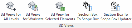
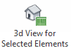
Find 3D View for Selected Elements on the Bonus Tools Ribbon or use 115 Search Tools.
Step 1 — Configure the view options
The dialog appears with two controls:
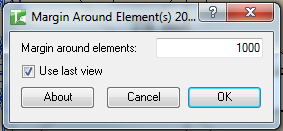
| Field | Description |
|---|---|
| Offset | The margin in project units added to all sides of the element bounding box (e.g. 500mm) |
| Use Last View | Tick to update the previously generated view rather than creating a new one (default: checked) |
Offset — Enter a value in the project's current length units. A larger offset reveals more surrounding context; a smaller offset isolates only the selected elements. Typical values: 300mm for tight inspection, 1000mm for broader context.
Use Last View — When checked, the tool overwrites the view it created last time (identified by the saved view name). Useful for repeated inspection of different selection sets without accumulating views. When unchecked, a new view is created on each run.
Step 2 — Create the view
Click OK. The tool:
- Computes the combined bounding box of all selected elements
- Expands it by the specified margin on all six sides
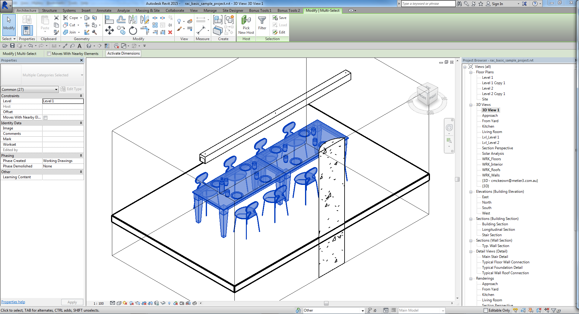
- Creates (or updates) an isometric 3D view with a section box matching the expanded bounding box
- Opens the view automatically
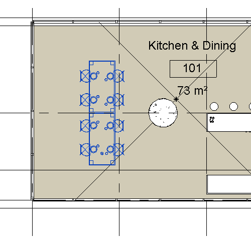
The new 3D view opens showing the selected geometry isolated within the section box:
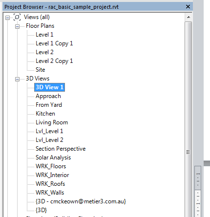
If Use Last View is unchecked, a new view is added to the Project Browser:
Tips and Best Practices
- Assign a keyboard shortcut for speed. This tool is most useful when bound to a shortcut key — select elements, press the shortcut, adjust offset, and press Enter. The entire workflow takes a few seconds.
- Use Last View to avoid view accumulation. With Use Last View checked, repeated runs replace the same view rather than creating a new one each time. Keep it unchecked only when you want to preserve a specific view for documentation.
- Select across multiple categories. The bounding box calculation works on any mix of element types — select a wall, the windows in it, and the adjacent column to see all of them together in the generated view.
- Increase the offset for context. A small offset isolates tightly; increasing to 1000mm–2000mm brings in surrounding context that helps with coordination discussions.
- The tool requires a pre-selection. Run it from within a 2D plan, section, elevation, or 3D view — any view where you can select elements first.
Common Use Cases
Quick element inspection — Select any element or group of elements and run the tool to open a 3D view showing only those elements in context. Ideal for checking connections, relationships, or clash resolution.
Coordination review — Select all elements in a clash zone from a plan or section, run the tool, and share the resulting 3D view with other disciplines for review.
Clash investigation — In Navisworks or Revit, identify clashing elements by ID, select them in the Revit model, and generate a section-boxed 3D view for investigation and documentation.
Documentation snapshots — Select the elements for a detail or assembly, generate a 3D view with a tight margin, and place it on a sheet for documentation.
Troubleshooting
"No valid elements selected." The tool was launched without any elements selected, or the selection contained only non-geometric elements. Select one or more model elements before running.
View is created but immediately replaced on re-run Use Last View is checked and the tool updated the existing view. Uncheck Use Last View before running to create a new view instead.
The section box is too tight or clips elements Increase the Offset value. A very small offset may clip elements whose geometry extends beyond their bounding box centre point.
"Operation Failed." An unexpected error occurred. Check the Revit journal for details.