103 Wall Direction
Chris McKeown / July 1, 2025
Time Saving
Overview
Wall Direction analyses each wall's geometry to determine the direction it faces — expressed both as a compass cardinal/ordinal point (N, S, E, W, NE, NW, SE, SW) and as a clockwise angle from North in degrees. The results are written back to any text parameter you choose on the wall element. This removes the need for manual orientation surveys or complex Dynamo scripts, and is particularly useful for projects with solar analysis requirements, façade specifications, or room data sheets that require wall orientation data.
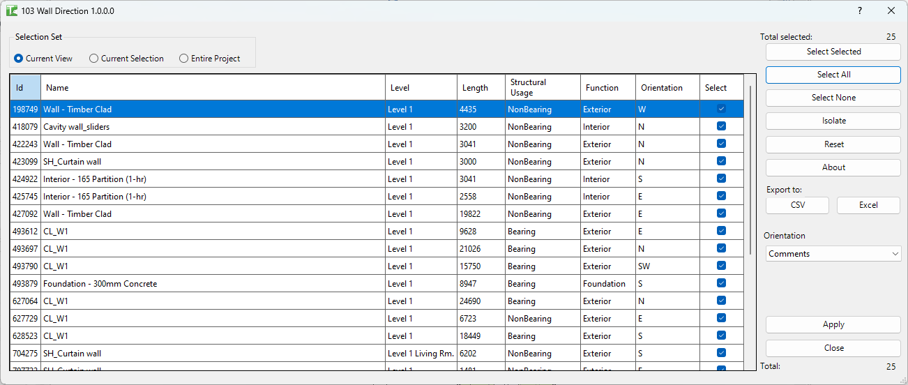
Table of Contents
Key Features
- Calculates wall facing direction as an 8-point compass orientation (N, S, E, W, NE, NW, SE, SW)
- Calculates clockwise angle from North (0–360 degrees)
- Three scope options: Current View, Current Selection, or Entire Project
- Grid columns: Id, Name, Level, Length, Structural Usage, Function, Orientation
- Write results to any compatible wall parameter via the Orientation and Angle dropdowns
- Apply button writes selected parameter values to all walls in the grid via sub-transactions
- Progress bar with Cancel button — cancelling stops processing (partial changes already committed are retained)
- Isolate button — selects the highlighted wall in the Revit canvas
- Export CSV / Export Excel for exporting the grid data
- Reset clears the grid back to its initial state
Requirements
- Must be run in a project document (not a Family document)
- The Orientation or Angle target parameter must be a text (or angle-compatible) parameter that exists on the Wall category
- At least one of Orientation or Angle must be selected before applying
- A valid Kiwi Codes Bonus Tools licence must be active
Running the Tool
Launch
Find Wall Direction on the Bonus Tools Ribbon or use 115 Search Tools.
Step 1 — Set the scope
Choose the Selection Set:
| Option | Behaviour |
|---|---|
| Current View | Analyses all walls visible in the active plan or 3D view (default) |
| Current Selection | Analyses only the wall elements currently selected in Revit |
| Entire Project | Analyses every wall in the model across all levels |
For large models, use Current View or Current Selection to limit processing time.
Step 2 — Review the calculated orientations
The grid populates with all walls in scope. Each row shows:
| Column | Description |
|---|---|
| Id | Revit element ID |
| Name | Wall type name |
| Level | The base level of the wall |
| Length | Wall length |
| Structural Usage | Wall structural usage (Bearing, Shear, etc.) |
| Function | Wall function (Interior, Exterior, Retaining, etc.) |
| Orientation | Calculated compass direction: N, S, E, W, NE, NW, SE, SW |
The orientation is derived from the wall's outward normal vector relative to True North. A wall facing roughly north (within 22.5° of north) is labelled N; at 45° increments the ordinal directions (NE, SE, SW, NW) are assigned.
Step 3 — Choose target parameters
Use the dropdowns below the grid to select which wall parameters receive the calculated values:
| Dropdown | Value written |
|---|---|
| Orientation | Compass string — e.g. N, NE, S — written to a text parameter |
| Angle | Clockwise degrees from North — e.g. 45.0 — written to a text or angle parameter |
Select <None> for either dropdown to skip writing that value. At least one must be set to a real parameter before clicking Apply.
Step 4 — Apply
Click Apply. A progress bar tracks each wall. For each wall:
- A SubTransaction is started
- The selected parameter(s) are set to the calculated values
- The result is logged
When complete, a message reports: "X passed. Y failed."
Tips and Best Practices
- Create a dedicated shared parameter for wall orientation. Add a shared text parameter (e.g. "Wall Orientation") to the Wall category, then target it in the Orientation dropdown. This keeps the data portable across projects.
- Use Current View for floor-by-floor processing. On large projects, running per-floor plan view is faster than Entire Project and lets you verify results level by level.
- Export before applying. Use Export CSV/Excel to capture the calculated values in a spreadsheet before writing them to Revit — useful as a QA record.
- True North vs Project North. Wall Direction calculates against True North as defined in the Revit project (via the site plan's True North rotation). Ensure your project's True North is correctly set before running.
- Curved walls. The orientation is calculated from the wall's tangent direction at its midpoint. Curved walls with significant arc may return an averaged orientation.
Common Use Cases
Façade specification tagging — A facade consultant requires each wall labelled with its orientation for solar gain calculations. Run Wall Direction on the exterior walls, write the Orientation value to a shared parameter, and include it in a wall schedule or on-sheet tag.
Room data sheets with orientation — Room data sheets require the wall orientation for each bounding wall. Write the compass value to a parameter and pull it into the room schedule.
Solar analysis preparation — Export the grid with wall IDs, lengths, and orientation values to Excel for input into an external solar shading analysis tool.
Construction-phase orientation marking — During construction, site teams need cardinal directions on elevation sheets. Apply orientations to a parameter and add a wall tag to display it on the relevant views.
Troubleshooting
"Select to write at least Angle or Orientation"
Both dropdowns are set to <None>. Select a target parameter in at least one of the Orientation or Angle dropdowns before clicking Apply.
"Apply Wall Orientation/Angle failed. Gain ownership of elements and try again." In a workshared model, some walls are owned by another user. Request or borrow ownership (or Synchronise and reload) and try again.
Orientation shows an unexpected direction Check the project's True North setting (Manage → Project Location → Position). If True North differs significantly from Project North and has not been configured, orientations will be relative to project north by default.
Grid is empty No walls were found in the selected scope. For Current View, ensure the active view is a plan or 3D view that displays walls. For Current Selection, ensure walls are selected before launching.
"X passed. Y failed." with failures Check the Output log for red entries. Common causes include the target parameter being read-only, not existing on the Wall category, or the wall having a null geometry location.