009 3D Views for All Levels
Chris McKeown / July 1, 2025
Sheet & View Manipulation
Overview
3D Views for All Levels creates one isometric 3D view per level in a single operation, naming each view Lvl_[LevelName] and applying a section box from the level elevation up to a configurable offset. Camera azimuth and altitude are adjustable. On multi-level projects this eliminates the repetitive work of setting up individual 3D views and manually adjusting section boxes for each floor.
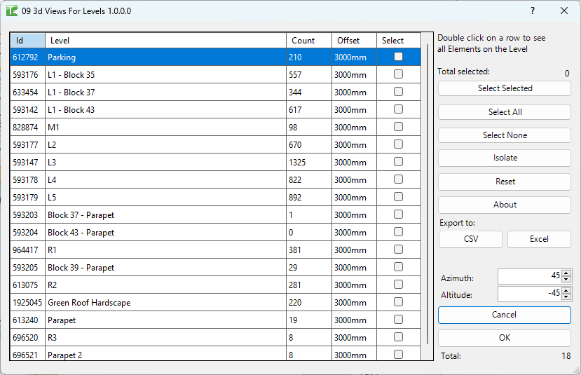
Table of Contents
Key Features
- Lists all levels in the project sorted by elevation, with an element count per level
- Offset field (per row) — section-box height above the level; default 3000mm
- Camera controls — Azimuth and Altitude numerics to set the isometric view direction
- Views named
Lvl_[LevelName]— easily located in the Project Browser - Detail Level set to Fine on all created views
- Multi-select — create views for any combination of levels in one click
- Select Selected / Select All / Select None for fast selection
- Double-click a row to view elements on that level via the element viewer
- Transaction: "3d Views" with per-level sub-transactions
- Confirmation: "X passed. Y failed."
Requirements
- Any Revit project document containing levels
- A valid Kiwi Codes Bonus Tools licence must be active
Running the Tool
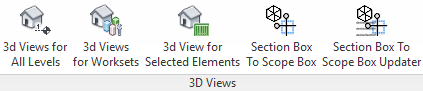
Launch
Find 3D Views for All Levels on the Bonus Tools Ribbon or use 115 Search Tools.

Step 1 — Review levels
The dialog loads all levels sorted by elevation:
| Column | Description |
|---|---|
| Id | Revit Element Id of the level |
| Level | The level name |
| Count | Number of elements associated with this level |
| Offset | Section-box height above the level in millimetres (default: 3000mm — editable) |
| Select | Checkbox — tick to include this level in the view creation run |
The Total counter at the bottom shows the total number of levels. Click any column header to sort.
Step 2 — Adjust offset and camera (Optional)
Offset — Controls how high the section box extends above the level's elevation. Edit the Offset value in any row to set a custom depth for that level. Typical values:
3000mm— standard floor-to-floor height, shows structure on the level5000mm— captures tall plant spaces or equipment above the slab
Camera — Use the Azimuth and Altitude numeric inputs to set the view direction for all created views:
- Azimuth: horizontal rotation (0° = North)
- Altitude: vertical viewing angle
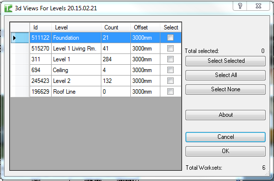
Step 3 — Select levels
Tick checkboxes in the Select column, or use the selection buttons:
| Button | Action |
|---|---|
| Select Selected | Toggle the checkbox for the currently highlighted row(s) |
| Select All | Check all levels |
| Select None | Uncheck all levels |
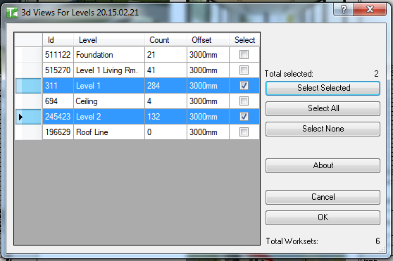
The Total selected counter updates as you make selections.
Step 4 — Create views
Click OK. A 3D view is created for each selected level. A confirmation dialog reports the result:
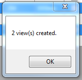
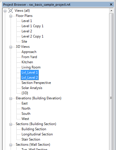
The new views appear in the Project Browser under 3D Views with the Lvl_ prefix:
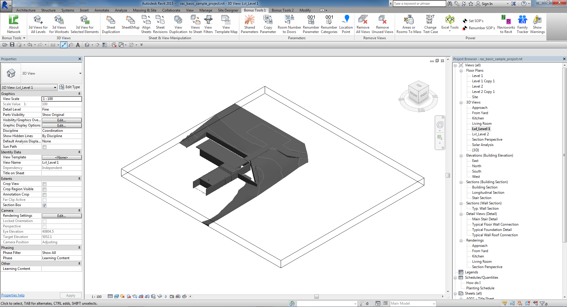
Opening any generated view shows the 3D geometry within a section box bounded to that level:
Tips and Best Practices
- Increase the Offset for mechanical or high-bay levels. A 3000mm offset may clip tall equipment or structural frames above the slab. Increase the offset for plant room or high-bay levels before running.
- The Lvl_ prefix keeps generated views grouped. All views sort together under
Lvl_in the Project Browser — easy to locate and easy to delete as a batch if regeneration is needed. - Re-run after adding levels. The tool does not modify or delete existing
Lvl_views — re-running creates new views for any new levels. Delete obsoleteLvl_views manually if needed. - Use Select All for the initial full-project run. On first use, generate the complete set; on subsequent runs, select only new or changed levels.
- Delete existing Lvl_ views before regenerating with new settings. If you need different offsets or a different camera angle, delete the existing generated views first, then re-run.
- Double-click a level row to check its element count. The element viewer shows what is counted on a level — useful for confirming that a level with a low count is genuinely sparse before deciding whether to generate a view for it.
Common Use Cases
Initial project setup — At project start, run 3D Views for All Levels to create a standard set of level views for model reviews, coordination, and clash detection.
Coordination model review — Generate level views for every floor and share them with structural and MEP disciplines for per-floor coordination reviews.
Clash detection scoping — Section-boxed level views are an efficient way to scope a Navisworks or Revit clash detection run to a single floor, reducing noise from other levels.
Progress reporting — Create level views and use them as base views for progress snapshots or rendered images for client reporting at each floor level.
Troubleshooting
"X passed. Y failed." with failures Some views could not be created. In a workshared model, view creation may fail if another user holds ownership of the view tree. Gain ownership and retry.
"3D View Creation failed. Gain ownership of elements and try again." The transaction failed due to a worksharing conflict. Ensure you have the necessary permissions and retry.
"Operation Failed." An unexpected error occurred. Check the Revit journal for details.
A generated view's section box does not match the expected level Verify the Offset value set for that level before running. A very large offset may cause the section box to overlap geometry from adjacent levels.
Levels show Count = 0 The Count column reflects elements formally associated with the level via the Level parameter. Levels used for reference only (with no hosted elements) will show 0. Views are still created for these levels.
Re-running creates duplicate Lvl_ views
The tool does not check for existing Lvl_ views before creating new ones. Delete the existing generated views from the Project Browser before re-running if you need to regenerate them with updated settings.